Introduction
The LAT provides access to a 6 MV Pelletron Tandem accelerator as well as a 1.7 MV Tendetron accelerator. The tandem mode means that the ions are accelerated twice by the terminal voltage, doubling the ion energy. Negative ions are generated by the source, then injected into the terminal (beige tank on the picture). They are then first accelerated by the positive potential of the terminal. When they pass through the center of the accelerator, a stripper gas makes them lose electrons. They thus become positive ions, are pushed back by the positive potential and will accelerate another time, their energy being able to reach several MeV. They are then directed towards the chosen beam line.
| Accelerator | Max terminal voltage | Max proton energy | Max proton current | Energy resolution |
|---|---|---|---|---|
| Tandetron | 1.7 MV | ? | ? | ? |
| Pelletron Tandem | 6 MV | 11 MeV | 15 uA | ? |
The Pelletron Tandem accelerator is actually the first prototype of a Tandem accelerator in the world. Installed initially at Chalk River Laboratories in 1954, it was transferred to U. Montreal in 1966. A new source and a new charge system were installed in 2002.
MIL accelerator?
More information about the beam facilities at UdeM can be found here.

Material analysis
c-RBS (Channeling mode Rutherford Back Scattering)
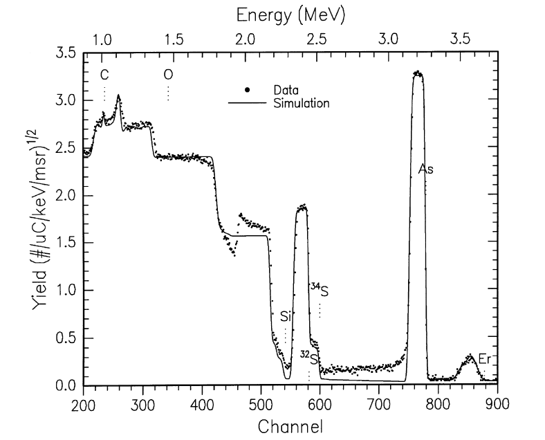
The best known ion beam analysis technique is Rutherford Backscattering Spectrometry (RBS). A light ions beam (H, He) with energy of 1 - 3 MeV impinges on the target. The ions backscatter from the near surface region of the sample and are collected by a solid state detector. The energy distribution of the backscattered ions provides information on both the composition and depth distribution of elements in the target. Thicknesses and composition of the different sample layers are deduced from their energy loss as they cross the sample. Composition and thicknesses are extracted by comparing experimental spectra to simulations. Ion beam analysis techniques are intrinsically quantitative and do not require a standard to compare to. In channeling mode, the alignment of the ion beam with sample crystallographic axes provides crystal defects lattice location.
The graph on the left shows an RBS measurement and a simulation of Er implanted in a chalcogenide layer deposited on SiO2 (from Fick et al. J. Non Cryst. Sol. 272 (2000) 200.) Since the different atoms have different masses, the ions are backscattered at different energies. The height of the peaks is proportional to the concentration of that element in the layer, while the width gives the thickness of the layer. RBS is straightforward, but as it can be seen on the graph, it can be difficult to distinguish close masses, and the signal form light elements (e.g. C, N, O) is small and pilled on top of the substrate signal. Plus, H is undetectable with this technique. Also, much better depth resolution can be achieved with a special detector and by working at lower energies.
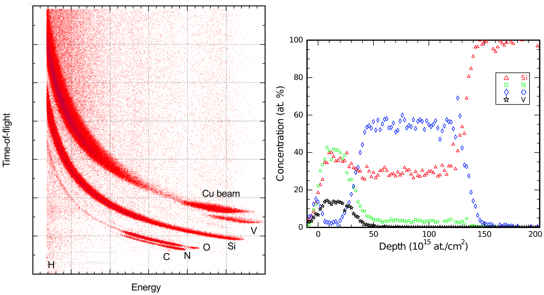
ERD-TOF (Elastic Recoil Detection - Time Of Flight)
In order to solve the sensitivity problem to light elements, and to actually separate the signal from the different target atoms into different spectra, rather than detecting the backscattered ions, we can detect the other particle involved in the collision: the recoil. That's what is called Elastic Recoil Detection (ERD). However, these events have to be distinguished from the overwhelming contribution from the scattered beam. In the graph, the analysis of an oxynitride is achieved by measuring the Time of Flight of the recoils and scattered atoms, hence ERD-TOF. We see that the recoil events from the light elements are clearly separated from the other signals, and that H is detected. The small amount of N in the oxynitride (between depth 50 and 140) would have been very difficult to detect and simulate by RBS. Hence, this technique is powerful for quantitative depth profiling of hydrides, carbides, nitrides and oxides, but is also useful in general for the analysis of compounds.
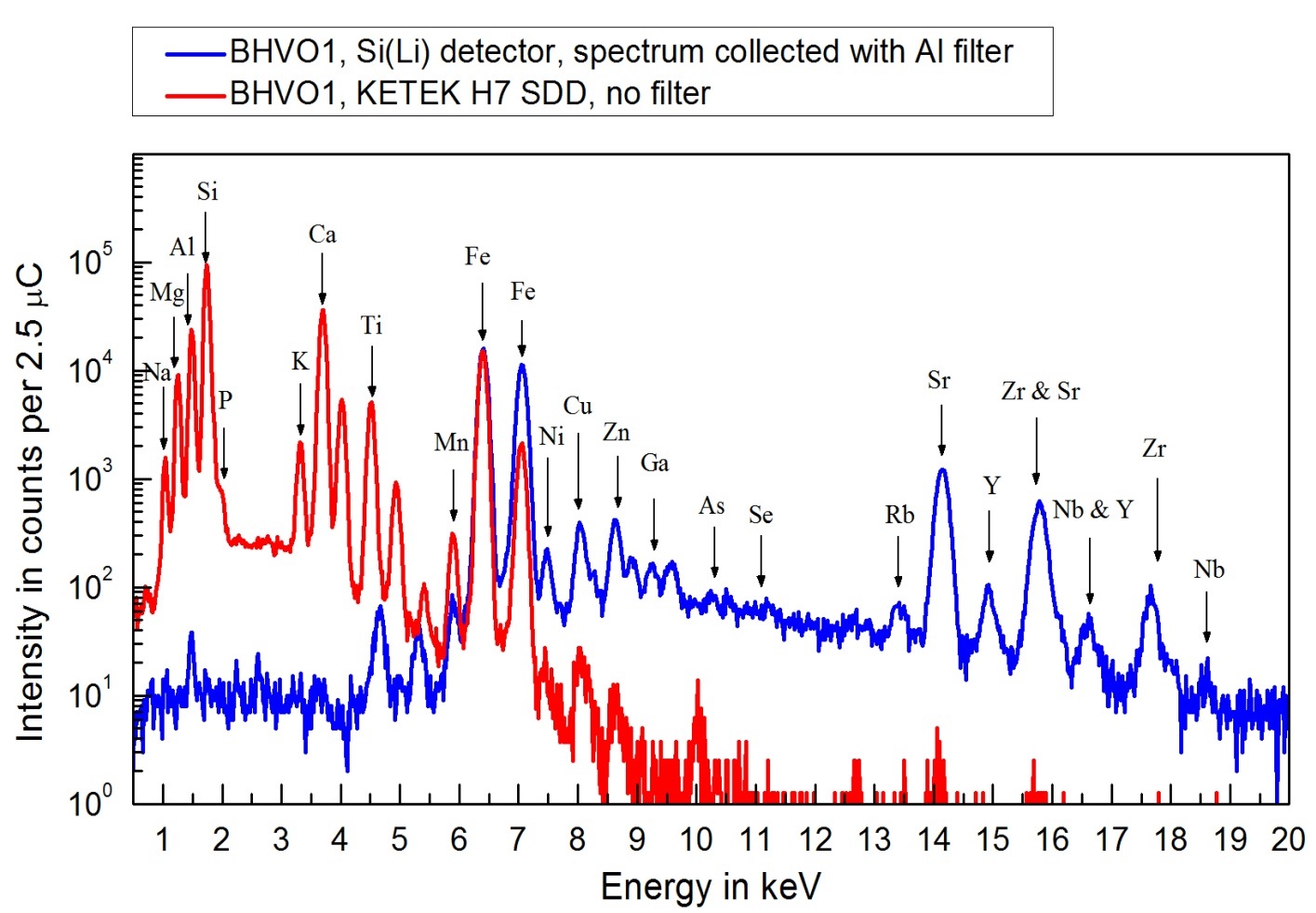
μ-PIXE (Particle-Induced X-ray Emission)
While distinguishing elements with close masses is achieved easily for light elements by ERD-TOF, this is not the case for heavier elements. This, and finding trace impurities in a quantitative way, can be achieved by particle induced X-ray emission (PIXE), which relies on the X-ray emission by the target atoms in order to identify them. Proton beam currents of a few nA suffice to provide rapid accumulation of spectra in two detector types: SDD for K X-rays of light (Z≥11) major and minor elements; Si(Li) for X-rays of heavier trace elements. In our newer proton microprobe the analysis chamber is being constructed to accomplish both simultaneously. The widely used GUPIXWIN software developed at Guelph fits the spectra and converts X-ray peak areas to element concentrations with a rigorous treatment of matrix effects. In the example shown, for the geochemical reference material BHVO1, the red spectrum is from the major and minor elements and the blue one from the trace elements. Derived concentrations in this case are accurate at the ~ 1 - 2 % level. Better depth resolution for ultra-thin layers can be obtained by using electrostatic detector and lower energy beam. Medium Energy Ion Scattering (MEIS) is targeted as such cases.
Detector calibration
The accelerator facility is able to produce protons, neutrons as well as a multitude of ion beams. The beams are available for the local Physics Department, but also open for external clients sin the beam time if not fully booked by our researchers. The neutron beam line is equipped with an NMR magnet analyzer system providing mono-energetic neutrons via (p, n) reactions with keV energy resolution. A low energy neutron spectrometer is presently installed and used by PICO and SuperCDMS dark matter experiments at a dedicated beam line which allows unique, high precision calibrations of dark matter experiments by tagging mono-energetic nuclear recoils.

Clean room

Target preparation
People

The facility is maintained and operated by a Fabrice Debris (B.Sc. Physics). He has a lot of experience in particle physics and also has a background in electrotechnics. The implantation and sample analysis is performed by Martin Chicoine (Ph.D. Physics), our local research agent. Prof. Sjoerd Roorda (Ph.D. Physics) and prof. François Schiettekatte (Ph.D. Physics) are running the facility, both experts in ion beam modification and analysis of materials.
Cost
Implantation or calibration
This table shows the fees for using one of the beams, either for target implantation, detector calibration or other beam usage.
Client | 4 hrs w/o operator | Full day w/o operator | 4 hrs with operator | Full day with operator |
|---|---|---|---|---|
UdeM physics | Free | Free | Free | Free |
Academic | N/C | 200$ | 400$ | 700$ |
Industrial | N/C | N/C | 1000$ | 2800$ |
Sample analysis
This table shows the fees for sample analysis using the different techniques available at our facility.
Client | RBS or PIXE | ERD |
|---|---|---|
UdeM physics | Free | Free |
Academic | 200$/sample | 400$/sample |
Industrial | 500$/sample | 800$/sample |
Contact
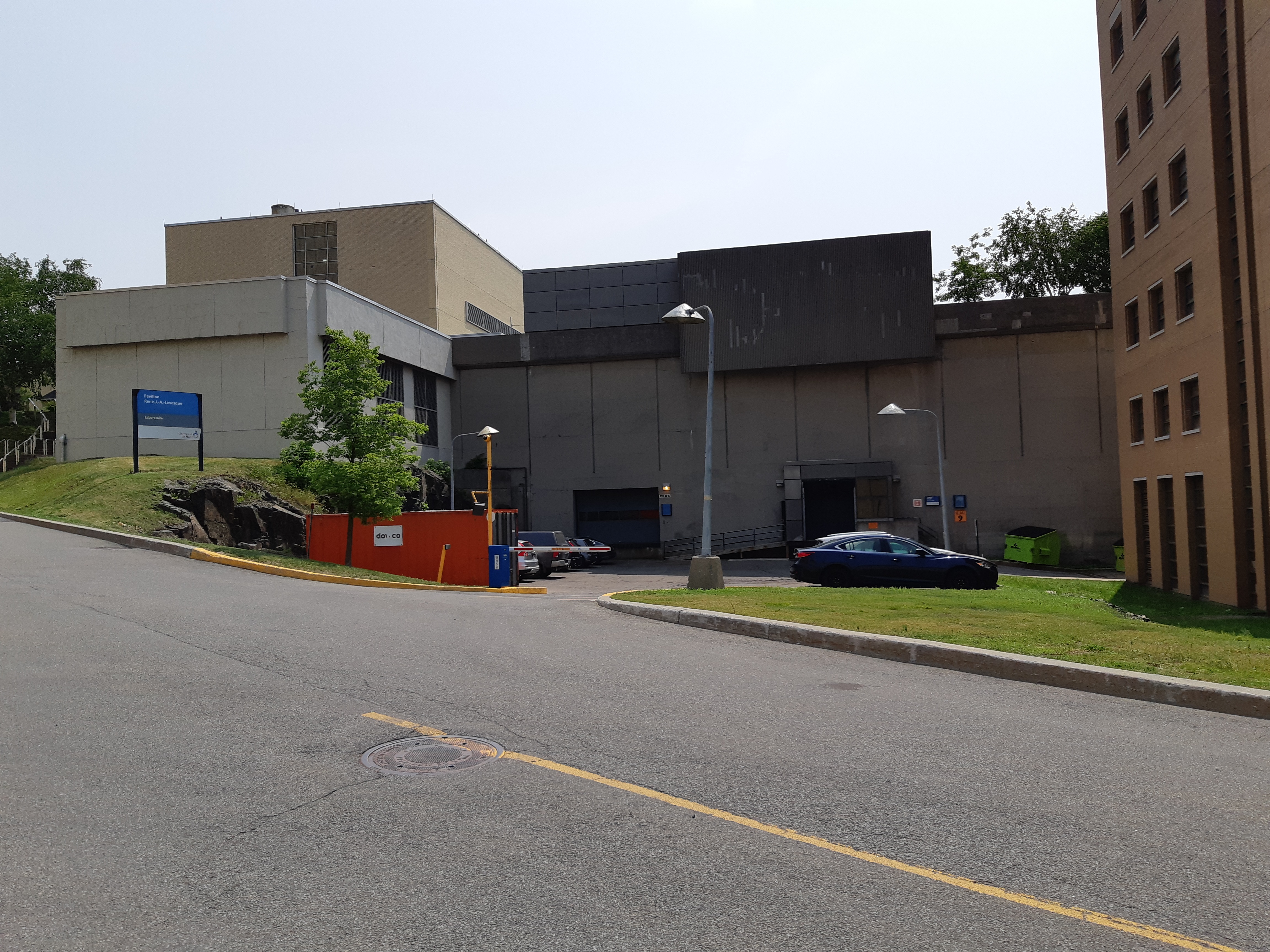
The ion beam facility is located in the Laboratoire René J.-A. Lévesque on the main campus of Université de Montréal. The address is
- 2905 chemin des Services
- Laboratoire René J.-A. Lévesque
- Montréal, Qc
- H3T 1J4
You can join our team by phone 514-343-6111 #XXXX or by e-mail at XXX@umontreal.ca
Temporary

