- Created by Nicolas Stifani, last modified on Jan 30, 2024
You are viewing an old version of this page. View the current version.
Compare with Current View Page History
« Previous Version 17 Next »
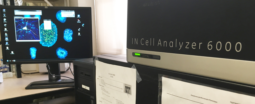
GE InCell Analyzer 6000 High content microscope
JA Bombardier Building, Room 3129
Instrument awarded to Dr. Steve Michnick by the Canadian Foundation for Innovation (CFI)
Advanced Microscope Tier 2 usage price
- Applications
- Transmitted light, Bright-field
- Pseudo phase contrast and DIC
- Fluorescence
- High-throughput imaging
Light sources
LED for transmitted light
Toptica iChrome MLE for fluorescence
Source | Polychroic | Excitation wavelength (nm) | Compatible fluorophores | Nominal Power (mW) |
---|---|---|---|---|
405nm | 390/40 | [370-410] | DAPI, Hoechst | 50 |
488nm | 482/18 | [473-491] | FITC, GFP, YFP | 25 |
561nm | 564/9 | [559-569] | Cy3, DsRed, TxRed | 30 |
642nm | 640/14 | [632-647] | Cy5, Cy5.5 | 50 |
Objectives
- 10x/0.45 Air WD 4.0
- 20x/0.75 Air WD 1.0
- 40x/0.6 Air WD 2.7-3.7
- 60x/0.95 Air WD 0.15
Position | Name | Brand | Full name | Identifier | Working distance (mm) | Transmittance (% [nm]) | Techniques | Cover glass thickness (mm) |
---|---|---|---|---|---|---|---|---|
1 | 10x/0.45 Air | Nikon | 10x/0.45 Air | MRD00101 | 4.0 | >80% [TBD-TBD] | BF, p-PhC, p-DIC, Fluo | 0.17 |
2 | 20x/0.75 Air | Nikon | 20x/0.75 Air Plan Apo DIC N2 M25x0.75 | MRD00201 | 1.0 | >80% [TBD-TBD] | BF, p-PhC, p-DIC, Fluo | 0.17 |
3 | 40x/0.6 Air | Nikon | 40x/0.6 Air Plan Fluor ELWD M25x0.75 | MRH08430 | 2.7-3.7 | >80% [TBD-TBD] | BF, p-PhC, p-DIC, Fluo | 0.17 |
4 | 60x/0.95 Air | Nikon | 60x/0.95 Air Plan Apo M25x0.75 | MRD00600 | 0.15 | >80% [TBD-TBD] | BF, p-PhC, p-DIC, Fluo | 0.17 |
BF: Bright-field
p-PhC: Pseudo-phase contrast
p-DIC: Pseudo-Differetial interference contrast
- Filters
DAPI
GFP
Cy3
Cy5
- Cy5.5
Position | Name | Brand | Identifier | Polychroic (Transmission) | Emission filter | Efective bandwith (nm) |
---|---|---|---|---|---|---|
1 | DAPI | TBD | TBD | BP 420/20 [430-462] | 455/50 [430-480] | [430-480] |
2 | GFP | TBD | TBD | BP 446/32; 524/42; 600/36; 732/137 | 525/20 [515-535] | [515-535] |
3 | Cy3 | TBD | TBD | BP 446/32; 524/42; 600/36; 732/137 | 605/52 [579-631] | [582-618] |
4 | Cy5 | TBD | TBD | BP 446/32; 524/42; 600/36; 732/137 | 707/72 [671-743] | [671-743] |
5 | Cy5.5 | TBD | TBD | BP 446/32; 524/42; 600/36; 732/137 | 720/60 [690-750] | [690-750] |
- Detector
- sCMOS Monochrome 2560 x 2160 pixels, 16-bit, pixel 6.5um x 6.5um, sensor 16.6mm x 14.0mm
If necessary, turn on the microscope (#1)
Note
The switch is not easily accessible and is located on the back of the right side of the device.
- If necessary, turn on the computer (#2)
- Use your UdeM credentials to log in to Windows
Start the software IN Cell Analyzer 6000
Within the software IN Cell Analyzer:
- Click Eject to open the access door
- Insert your sample in the space provided for this purpose, respecting the orientation indicated
Click Load to close the access doors
First use
During the training you will follow the First use protocol
Important
For use with the 60x objective it is absolutely necessary to use a multi-well plate with a glass bottom. The glass thickness should be 0.17mm. We recommend the following plates:
- Collect your samples
- Click Load to close the access door
- Close the INCell Analyzer software
- Transfer your data to disk D: (Data Storage) or to your external hard drive and delete it from local disk C:
- Turn off the computer
Important Reminders
- Collect your samples, especially those in the microscope
- Leave the microscope and workspace clean
- Files can be saved temporarily (during acquisition) to local C: drive (desktop)
- At the end of each session, copy your data to your external drive and delete it from local C: drive
- You can store your files on the D: drive (Data Storage). If you do, please create one folder per laboratory using the principal investigator's last name. Inside, create a folder per user using the following nomenclature (First Name_Last Name).
Important
In any case, do not store your files on the C: drive.
When using the microscope for the first time, it is necessary to define the type of plate used. You will usually do this during the training session .This procedure can also be performed if you are using a different multi-well plate.
Create a new plate
In the INCell Analyzer software:
- Select from the menu Application>Plate\Slide Manager...
- Click on the New Plate\Slide icon
- Select the number of wells in your plate (6, 24, 96 etc...)
- Adjust the following settings:
- Name: Your-Name_Your-Plate
- Plate height, bottom thickness and well volume usually provided in the product technical sheet by the manufacturer
- The material used plastic or glass
- If necessary adjust the number of rows and columns as well as the shape of the well (round or rectangular)
- Click OK
- Close the Plate/Slide Manager window
Measure the bottom height and thickness of the plate bottom
In the INCell Analyzer software:
- Click on the Dashboard
- In Objective Lens select the 10x objective
- On the plate plan, click on the center of a well containing a sample to center this well on the objective
- In the Dashboard menu select Plate/Slide
- Click Verify LAF
- If the 2 detected peaks (blue vertical lines) correspond to the measured peaks (black curve)
- Click Apply Measured Parameters
- Click OK
- Click Yes
- If the 2 detected peaks (blue vertical lines) do not correspond to the measured peaks (black curve)
- Change the bottom thickness value and repeat the operation
- Close the Laser Autofocus Plate/Slide Verification window
Measure A1 well offset
In the INCell Analyzer software:
- if necessary, click on the Dashboard > Objective Lens select the 10x objective
- In the channel list, click the + button and add a transmitted light channel (brightfield)
- To the right of the plate layout, click the Setup Preview Imaging button
- Draw a rectangle around well A1
- Click on preview (on the acquisition panel at the top right of the screen)
- Wait for the preview to be generated
- On the plate map, click on the real center of well A1 to center this well on the objective
In the Dashboard menu select Plate/Slide
Click Edit Plate then Define Upper Left Well
Click Yes
- Check that the yellow circle matches the edges of the well
Click Yes
Compute the inter-well distance
Repeat the offset measurement steps for the bottom right well
- The inter-well distance will then be automatically calculated
The following diagrams allow you to follow the light path in transmitted light (bright field) and in reflected light (fluorescence). These diagrams will be available soon.
Available manuals
Because of an issue with the liquid handling motor, the liquid handling arm as been replaced by a standard fixed arm for the transmitted light LED. Therefore liquid handling is no longer available.
Y motor not resting when reaching the transmitted light position: This time the issue is slightly different: Y motor is homing properly during the initialization procedure but instead of resting it keeps pushing toward the home position and after a brief instant the instrument stops and the red light shows up. If the liquid handler Y motor is disabled the initialization proceed properly and the system is usable at the exception of the brightfield of course
- Added to wiki
Instrument Serial W24318-1493815 BK02029
Service Password apiAWL
Troubleshooting
Usually, this microscope displays a green light when operational and an orange light when in use. A red light is on means the microscope is not functional. In this case please contact the platform manager.
FAQ
Usually the microscope remains on. However, it is best to turn it off if not in use for a long time (weeks). To do this:
- Navigate to the menu Application > Hardware >
- Click Shutdown Instrument
- Wait for the microscope to turn off
- The software closes automatically
- No labels